2. FAQs
2.1. Failed to configure the charging pile to connect to another server?
You need to check if your server restricts access to a specific SN. If there are restrictions on the SN, you need to add the charging pile’s SN to the whitelist in advance. In addition, some servers may have SN rules, such as SN length limits, character restrictions, etc. If such requirements exist, please contact our sales team for firmware customization.
2.2. What is the IdTag “DirectWorkUser”?
“DirectWorkUser” is the IdTag carried by the charging pile when it automatically starts charging in plug-and-play mode.
After the customer connects to his own backend, if he wants to use plug-and-charge normally, he needs to add the IdTag in his own backend and allow the IdTag to charge.
2.3. What is a diagnostic log? How much can be stored?
The diagnostic log stores hardware operation data. It is stored when the working state changes and when the pile is abnormal. It can store 510k, about 1490 items. The content is as follows:
time: Wed Jan 10 10:32:24 2024,state: 2,CP state: 6,cp duty: 0.34,cp high: 5.95,cp low: -11.95,voltage(L1): 233.41,voltage(L2): 233.41,voltage(L3): 233.41,current(L1): 0.00,current(L2): 0.00,current(L3): 0.00,energy: 0.26,temp: 32.00,board temp; 34.00,+12V:12.00,-12V: -12.00,5V: 0.00,errorflag: 0x00000000,other: 0x00011020
2.4. Can the charging station limit the current?
The charging pile cannot control the current, it can only tell the car how much current it can use through the CP line, and the car will adjust its own charging power according to the CP signal. If there is a problem with the vehicle and it does not work according to the protocol and charges at a higher power, the overcurrent protection of the charging pile may be triggered, prohibiting charging.
Setting the maximum operating current can change the overcurrent threshold of the charging pile.
Through load balancing, solar mode and scheduling in ocpp1.6, adjusting the current is to adjust the CP signal and will not change the overcurrent threshold.
2.5. How to effectively provide feedback?
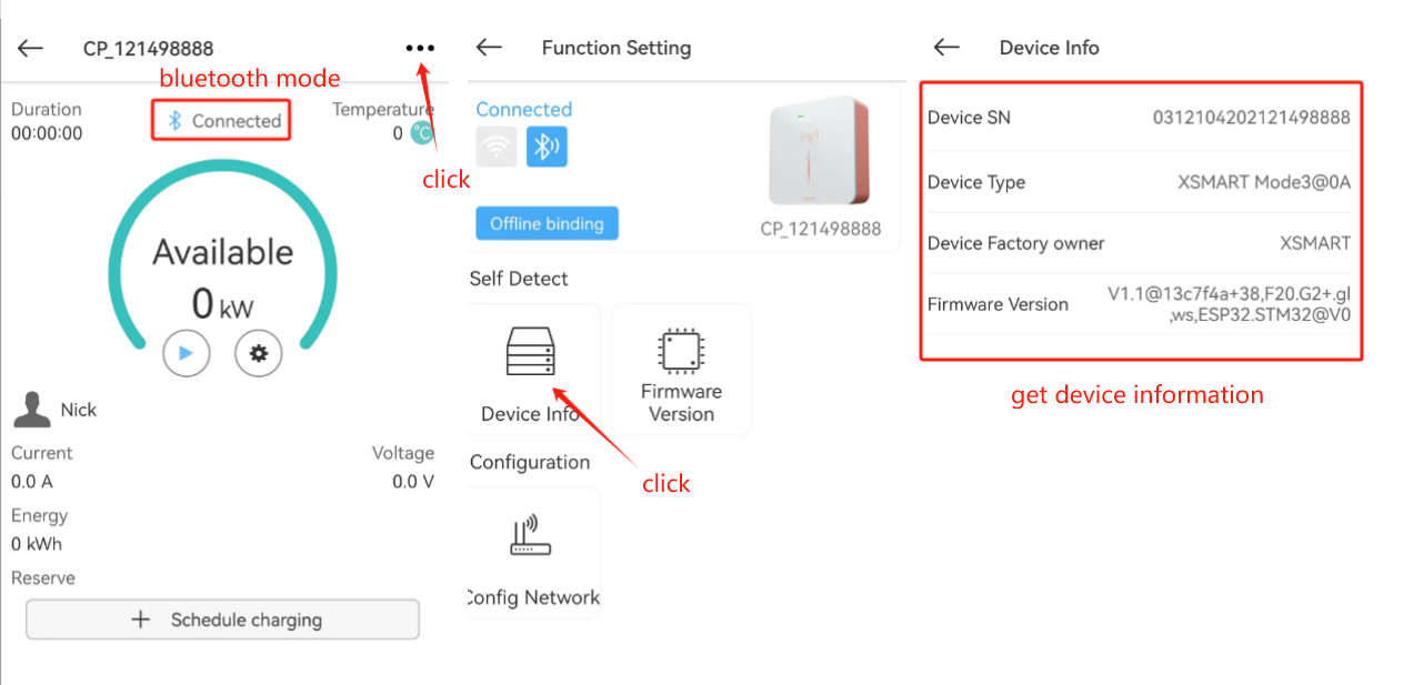
2.5.1. Connected to the Bluetooth
2.5.2. Connected to the network
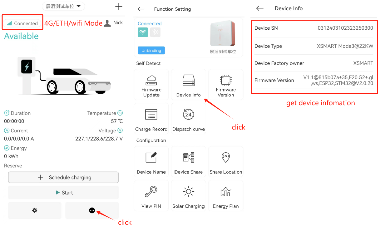
Important
Confirm whether the pile is online and connected to the XSMART backend.
2.6. X Smart download related matters?
Android: Google play search: X Smart by EVSE
App Store Search:X Smart by EVSE
2.7. Why is our WiFi connection easily disconnected?
Because our pile uses an onboard antenna, the receiving ability will be weaker than an external antenna.
2.8. Why does the charging record show “plug & play” after using scheduled charging?
When the scheduled charging starts at the start time, charging begins in a plug-and-play mode, so the charging record will show plug-and-play.
2.9. Are there any restrictions on the types of ICs?
Byte limit, card type requirements, etc.
Only 4-byte, 7-byte, and 10-byte (theoretical support, not verified) ISO/IEC 14443 type cards are supported.
2.10. Unable to charge and locate process
2.10.1. Rough analysis
2.10.1.1. Step 1: Please provide the following information when a fault occurs:
The color and color description of the vehicle charging port light (it will be on the inner cover of the vehicle charging port, but each car manufacturer has different definitions, so it needs to be provided);
Check whether the vehicle computer has any abnormal prompt information;
What is the status of the charging pile light, its color and flashing status, such as the red light flashing 6 times;
If the charging station has a screen, please take a photo of the information displayed on the screen;
2.10.1.2. Step 2:
If it is a national standard or American standard gun, please confirm whether the gun head button returns to its original position after insertion. This problem has been recorded many times. If it does not return to its original position, there will be problems with the CC link, which is equivalent to S1 not being closed, and the car will not respond at all;
Issues with the coupling between the gun head and the vehicle charging port. If the CC and CP contacts are not well connected, replugging the gun after lifting it can sometimes allow charging, indicating poor contact. Using an extension cable (preferably not from the same manufacturer as the original gun to avoid common mold process issues) can further support the identification of the problem.
2.10.2. Complete analysis method
2.10.2.1. Step 1: Use a multimeter to measure the resistance between CC and PE of the gun tip, and provide feedback pictures:
IEC resistance reference
CC IEC value standard |
||
Error interval MAX |
MAX |
4500 |
Section 13A |
MAX |
2460 |
Default |
1500 |
|
MIN |
1100 |
|
20A Section |
MAX |
936 |
Default |
680 |
|
MIN |
400 |
|
Section 32A |
MAX |
308 |
Default |
220 |
|
MIN |
164 |
|
Section 63A(three phase) |
MAX |
140 |
Default |
100 |
|
MIN |
80 |
|
Error interval MIN |
MIN |
60 |
2.10.2.2. Step 2: If you have an extension cord, you can use it first to see if it can charge normally; if it can, it means there is a problem with the coupling between the original gun head and the car charging socket;
2.10.2.3. Step 3: If you have a charger from the same manufacturer, please charge it to see if it can charge normally;
2.10.2.4. Step 4: If you have a charger from another manufacturer, please charge it to see if it can charge normally;
2.10.2.5. Step 5: In-depth analysis is divided into the following scenarios according to the test conditions:
Scenario A: With an oscilloscope, if the problem is with the motherboard, you can find the root cause.
Remove the charger from the case and use an oscilloscope to capture CP information. The oscilloscope probe should be clamped between CP and PE_OUT.
Power on the charger. If the network function is available, please stay online and open the DBGEnableInsight function in the background (refer to the DBGEnableInsight user manual);
If there is an Internet connection function, please turn off the plug-and-charge function in the APP;
Without the gun plugged in, observe the CP signal on the oscilloscope and take a photo to get feedback; — Check the accuracy of the 12V level
Insert the gun, observe the CP signal on the oscilloscope, take photos and report back; if there is any abnormality on the vehicle side, please also take photos and report back; — Check the accuracy of the 9V (6V) level
If it has Internet access, please start charging in the APP, observe the CP signal on the oscilloscope, take photos and report back; if there is any abnormality on the vehicle side, please also take photos and report back; — Check the accuracy of 9V PWM
If charging is possible, further observe the oscilloscope CP information, which should show a 6V level and 6V PWM. Take a photo and provide feedback. If there is an issue on the vehicle side, also provide a photo for feedback. — Check the accuracy of the 6V level and 6V PWM.
If there is network functionality and it is not an Xsmart platform, provide the log information from the above testing process.
Note: For points 4~7 above, it would be best to record a clear video.
Scenario B: No oscilloscope, but a multimeter—this method can help identify the root issue if it’s a motherboard problem.
Power on the charger. If the network function is available, please stay online and open the DBGEnableInsight function in the background (refer to the DBGEnableInsight user manual);
If there is an Internet connection function, please turn off the plug-and-charge function in the APP;
In the unconnected state, use a multimeter to measure the voltage between CP and PE, and provide a photo for feedback. — Check the accuracy of the 12V level.
Insert the gun, observe whether there is any abnormality on the vehicle side, take photos and provide feedback; — Verify whether the fault occurs at the 9V level
If the network function is available, please start charging in the APP, observe whether there is any abnormality on the vehicle side, and take photos for feedback; — Verify whether the fault occurs in 9VPWM
If it can be charged, observe whether there is any abnormality on the vehicle side and take photos for feedback; — Verify whether the fault occurs at 6V level and 6V PWM;
If there is network functionality and it is not an Xsmart platform, provide the log information from the above testing process.
Important
Note: For the above 4~6, it is best if you can record clear videos.
Scenario C: No oscilloscope, no multimeter - collect phenomena for analysis
Power on the charger. If the network function is available, please stay online and open the DBGEnableInsight function in the background (refer to the DBGEnableInsight user manual);
If there is an Internet connection function, please turn on the plug-and-charge function in the APP;
Plug in the gun, observe whether there is any abnormality on the vehicle side, take photos and provide feedback; — Verify whether the fault occurs at the 9VPWM level
If the vehicle reports an error in the previous step, please turn off the plug-and-charge function in the App;
Insert the gun, observe whether there is any abnormality on the vehicle side, take photos and provide feedback; — Verify whether the fault occurs at the 9V level
If there is no abnormality in the previous step, please start charging in the APP, observe whether there is any abnormality on the vehicle side, take photos and provide feedback; — Verify whether the fault occurs in 9V PWM
If it can be charged, observe whether there is any abnormality on the vehicle side and take photos for feedback; — Verify whether the fault occurs at 6V level and 6V PWM;
If there is network functionality and it is not an Xsmart platform, provide the log information from the above testing process.
Important
Note: For the above 4~6, it is best if you can record clear videos.
2.11. How to access the third-party OCPP platform?
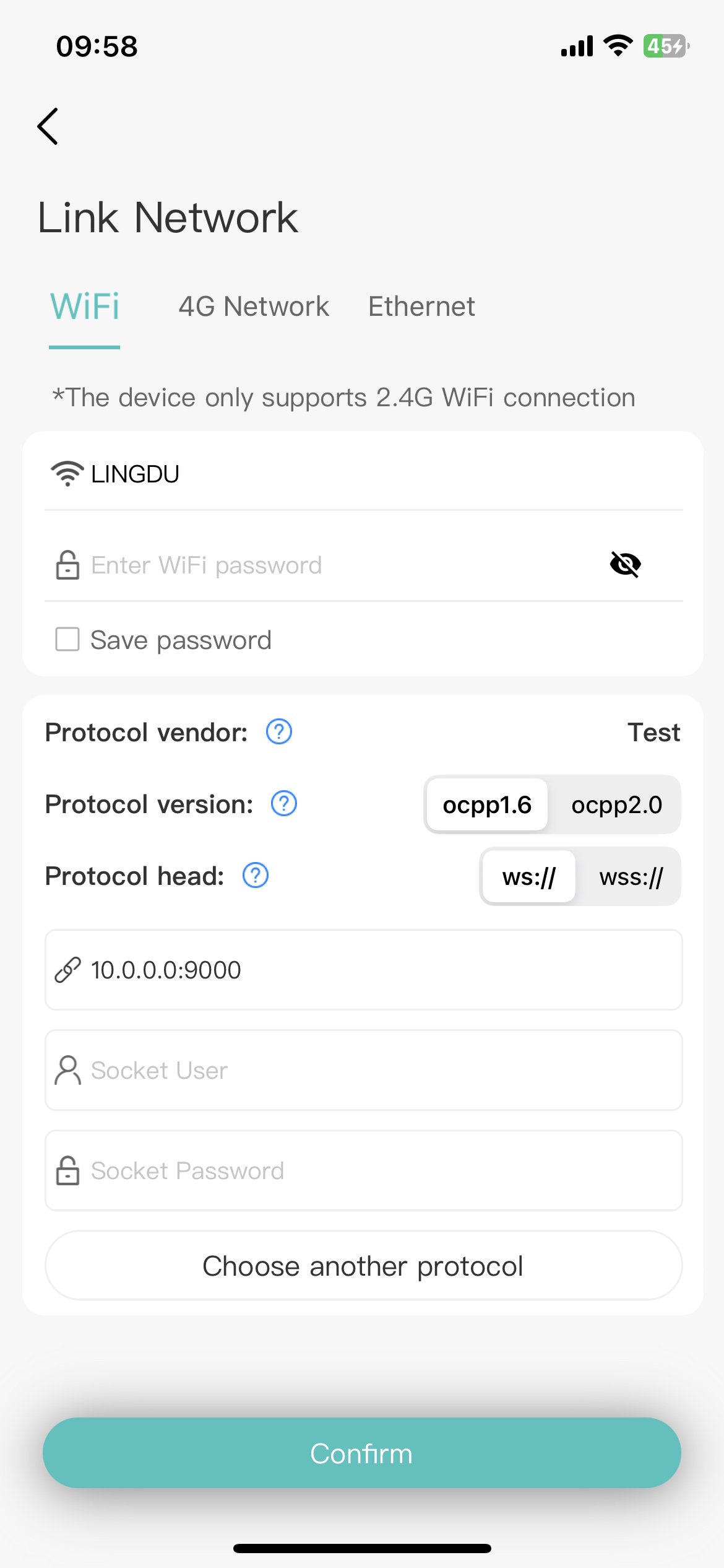
2.11.1. Step 1: Enter the pile distribution network interface, the following scene will be presented
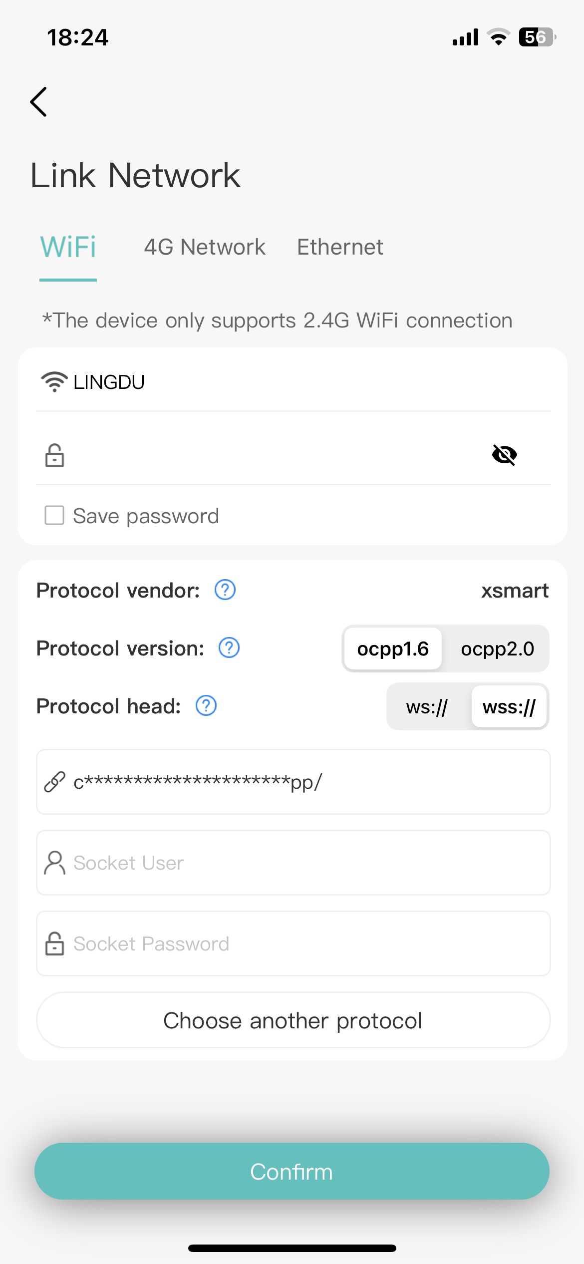
The device supports connecting to the target server via Wi-Fi, 4G network, or wired LAN port. This example assumes the device will connect via Wi-Fi. You need to select a 2.4GHz Wi-Fi network and enter the password for that Wi-Fi network.
We have configured a default Websocket configuration for you, and you can use this configuration to connect to our server. And you can get the best application experience and long-term device support.
If your device cannot configure the network using the default Websocket configuration, you can click “Select another protocol” to select another Websocket configuration for network configuration.
2.11.2. Step 2: After clicking “Select another protocol”, you will enter this page and connect using the Websocket address provided by the other OCPP server
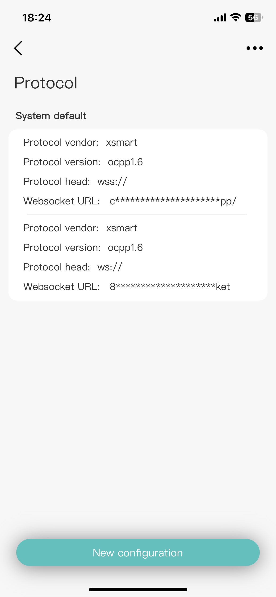
We provide you with two default addresses, “wss://” is an encrypted connection, and “ws://” is a non-encrypted connection
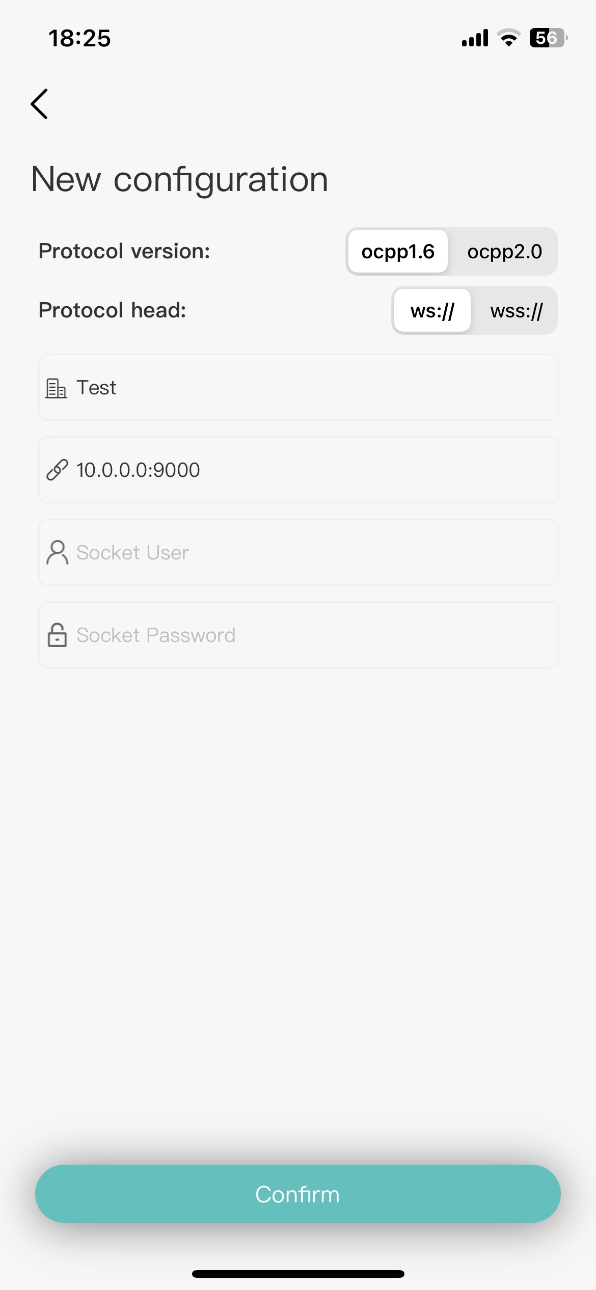
2.11.3. Step 3: After clicking “New Configuration”, you can fill in the Websocket address provided by other OCPP servers
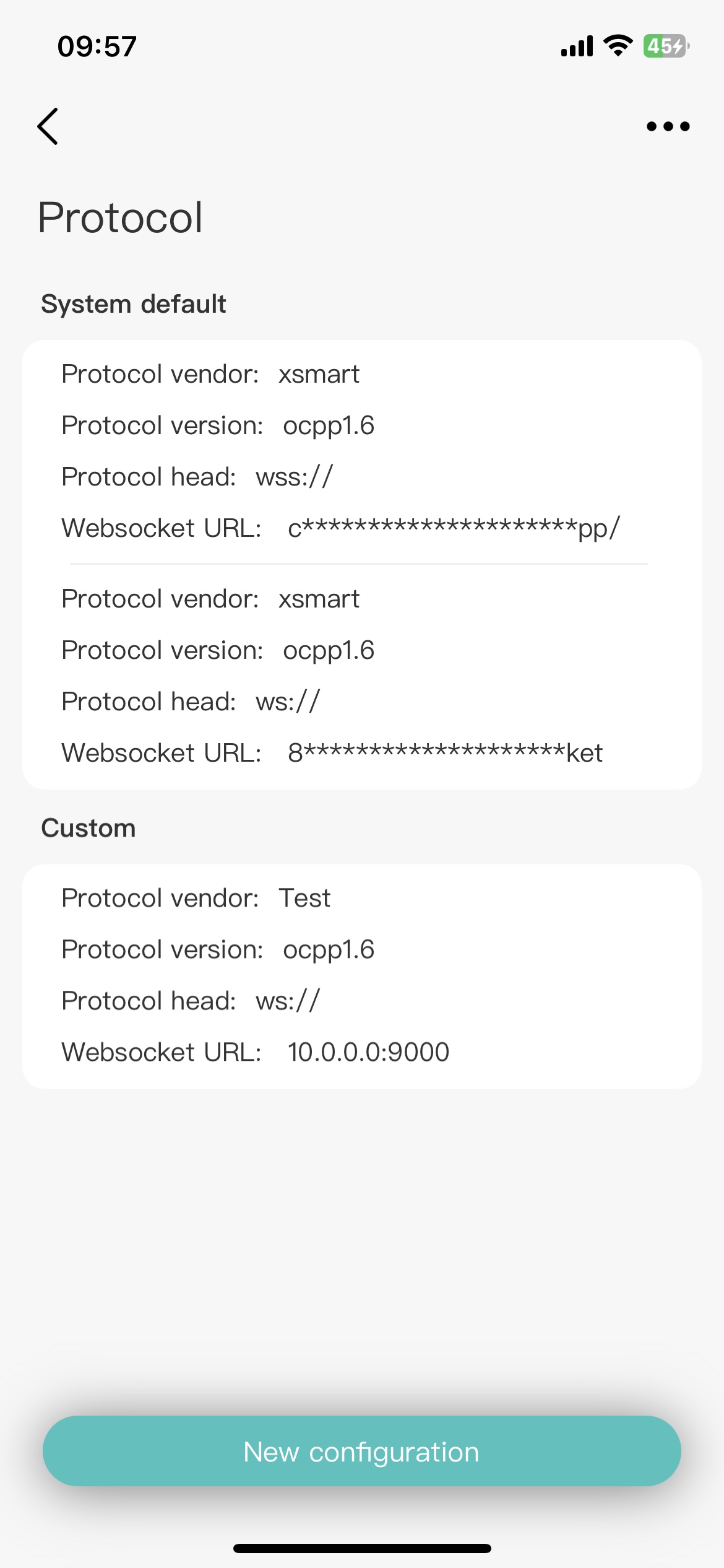
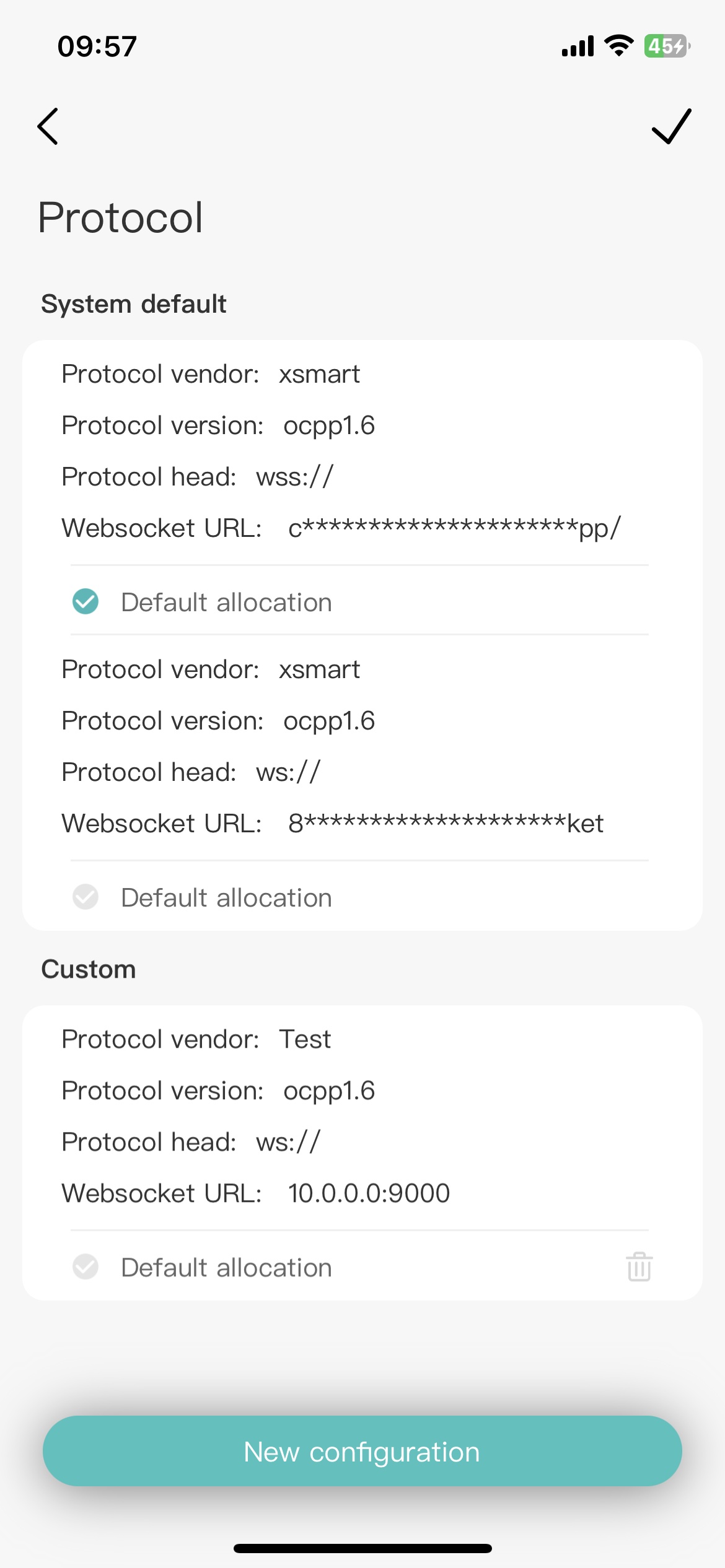
After adding, you can see the custom configuration in the protocol list. Click the button in the upper right corner to enter the “Edit” state. You can set the configuration as the default configuration or delete the custom configuration
2.11.4. Step 4: Click Custom Configuration to configure the device network using custom configuration
2.11.5. Step 5: Click on the network configuration, and after the prompt is successful, check whether the connection is successful by the following method
Please check whether the ball on the pile screen is always on. If it is, the network configuration is successful. Otherwise, the network configuration is not successful.
Secondly, you can check whether the connection platform can see that the pile is online
Important
Note: After successfully connecting to the third-party platform, it will not be displayed in the list on the homepage and cannot be controlled using the WiFi icon.
Terminology Note:
Term |
Describe |
|---|---|
Protocol Head |
wss is an encrypted connection, ws is a non-encrypted connection |
Protocol Vendor |
Server name or other convenient name to identify the server |
Protocol Version |
OCPP protocol version supported by the server (OCPP1.6/OCPP2.0) |
Websocket Password |
The socket communication password provided by the server |
Websocket URL |
The socket communication path and port number provided by the server |
Websocket User |
The socket communication account provided by the server |
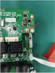
2.12. How do I restore factory settings?
With emergency stop: Press the emergency stop button, re-power the charging pile, wait for 2 seconds, and the emergency stop pops up; then press the emergency stop button (with an interval of 1 second) and the emergency stop pops up. Repeat the operation 6 times. After hearing a beep, the factory settings are restored successfully.
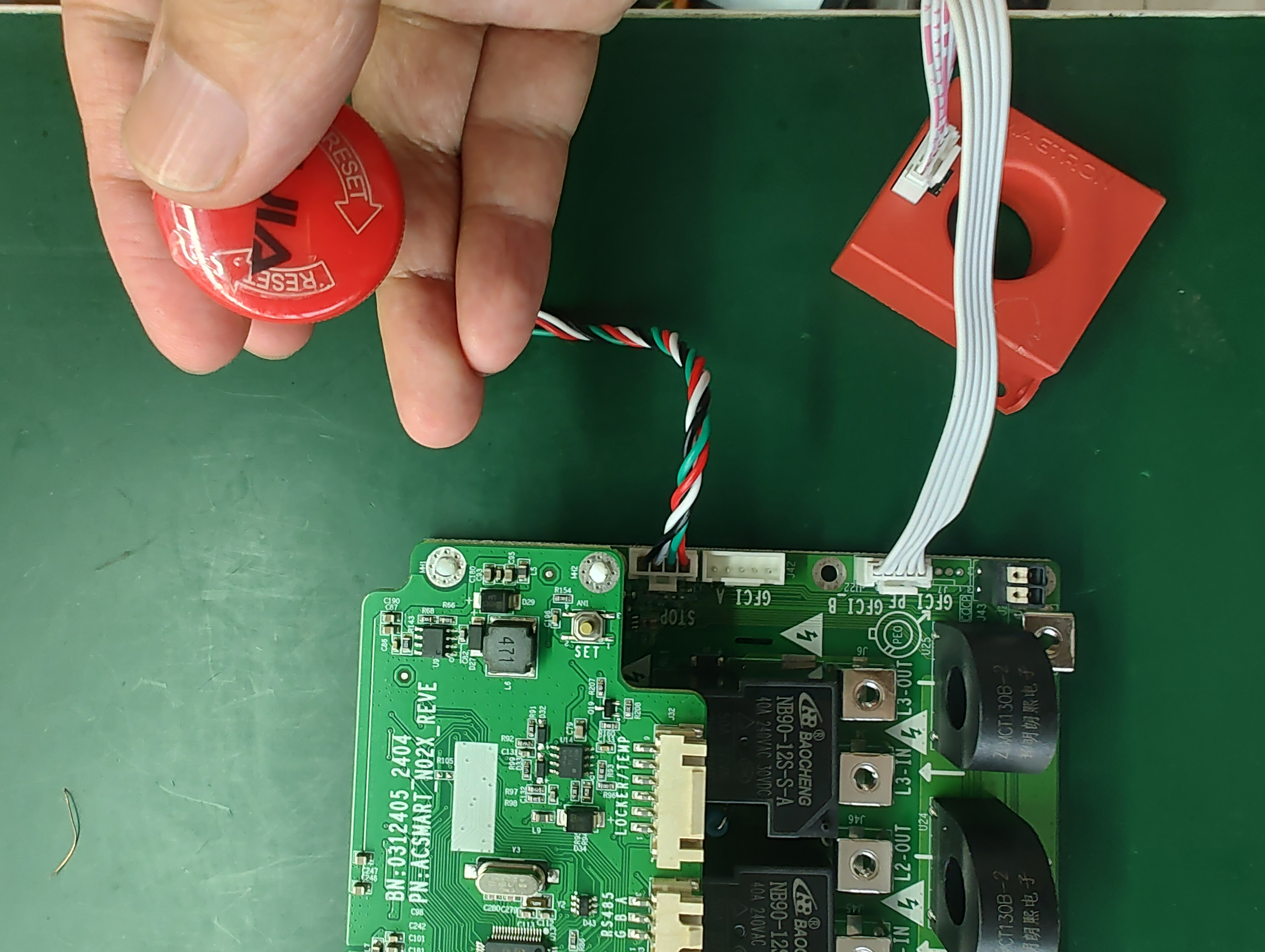
No emergency stop: Press the iron switch shown in the picture, power on the charging pile, wait for 2 seconds, then release the iron switch. Press the iron switch again, release it after a 1-second interval, and repeat the operation 6 times. After hearing a beep, the factory reset will b